Why did I need this
I started this project to be able to work around an issue I was having with my desktop PC, specifically I thought that it had something to do with the network port on the motherboard: as it turned out, I only had a faulty Ethernet cable! Replacing the cable solved the random disconnects and reconnects that I was experiencing.
That being said, I built the following system to be able to forcefully shut down and monitor the power state of that desktop PC, since I use it as a server and it is not in a comfortable position to reach for pressing the power button nor checking its status LED; I also found out that not all recent motherboards have Wake on LAN1 capabilities, so this might come in handy for another project.
Project specification
My requirements were the following for the device I wanted:
- let me control and monitor the power state of the connected computer
- to consume low power, since it would be always turned on
- to be secure/let me know what runs on it, since it will be connected to my router
- to be small, to fit it inside my computer’s case
- to be cheap
I could have used a smart plug to get most of the requirements listed, however I did wanted to try and get all of them through a DIY solution.
Since I have experience with Espressif’s ESP8266 family of microcontrollers, I chose the WeMos D1 Mini for building and programming the device I needed. Besides, they are awfully cheap: it’s worth it just for having fun with a Wi-Fi microcontroller project.
Hardware and schematics
I just needed a little bit of research through the Internet to learn that, to turn on or off a desktop computer and to report its state, two pairs of pins are used on the motherboard’s front panel connector header. The exact pin labels and position will vary depending on the specific motherboard, but in general the circuit I needed should:
- read the voltage across the power LED pins, to tell if it’s 0V or not
- close or open the circuit between the power button pins
Through another bit of researching, you will as well learn that both actions can be performed using BJT transistors in a simple configuration, for decoupling the microcontroller from the PC: after asking for advice to some more expert friends, the following is the final draft for the circuit diagram I used:
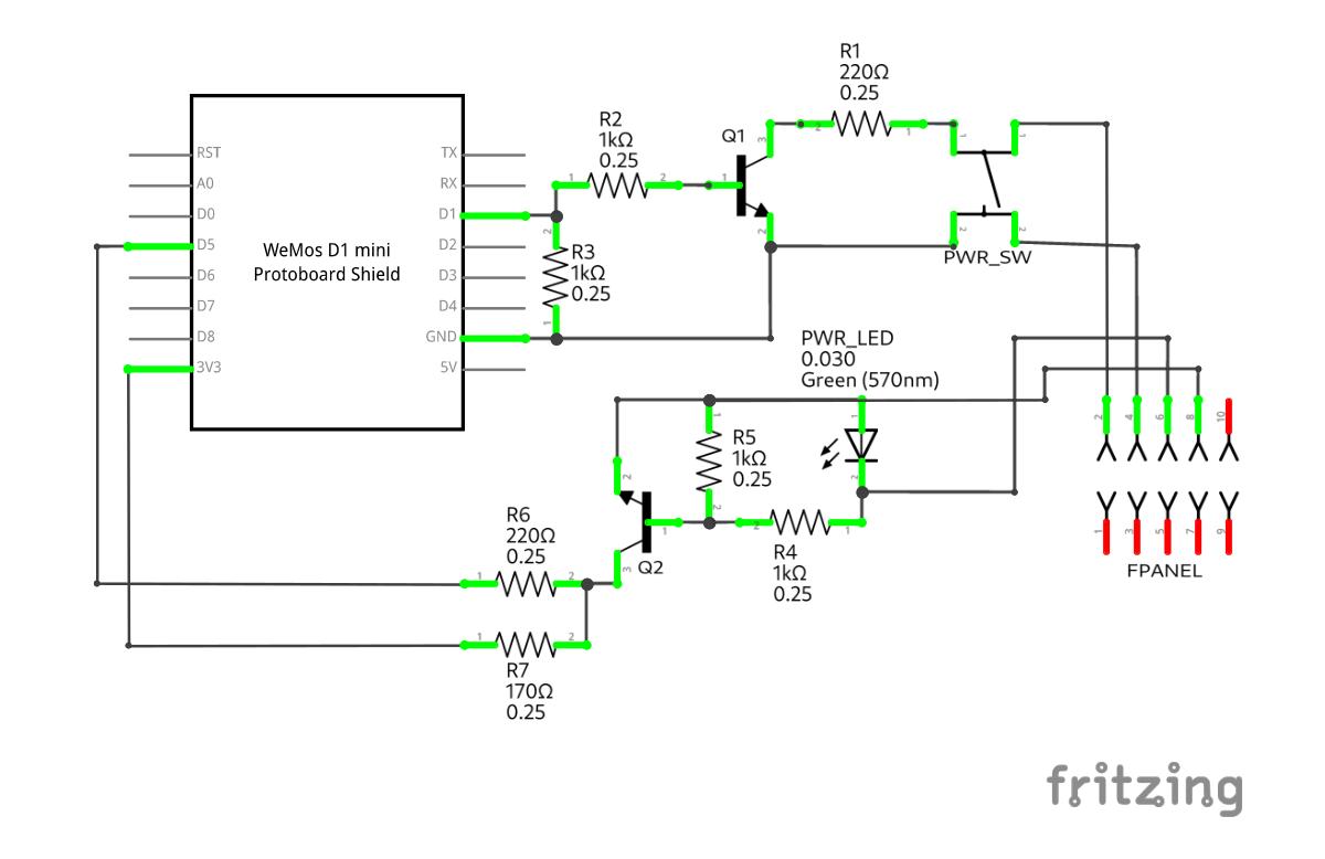
As you can see, Q1 and Q2 are the transistor components I mentioned: I used a pair of BC546 NPN BJTs2, since that is what I already had and they also seemed within spec. (always check the component’s datasheet); in my case, I looked for the maximum voltage drop across the terminals and the maximum allowed current.
NOTE: the arrow on the transistors inside the diagram is on the emitter terminal and pointing outwards, indicating the NPN polarization of both the components I used.
NOTE: the power LED (PWR_LED in the diagram) is a polarized component, therefore it must be connected to this circuit in the correct orientation3.
The resistors used does not need to be the same value, but it is important to keep their value ratio similar between R1, R2-R3, and R4-R5, R6-R7.
Circuit operation
The assumption for correct operation is that the microcontroller connected to the circuit (WeMos D1 Mini in the diagram) has a high voltage level of 3.3V and a low voltage level of 0V, and also the motherboard connected to the other end of the circuit (FPANEL in the diagram) operates a 5V or 3.3V.
In the configuration presented, there are two separate circuits based on the two transistors:
- the circuit around Q1 will allow current to flow through the terminals of the power button
- if the D1 pin of the microcontroller is pulled to high voltage
- the circuit around Q2 will let voltage rise to high on the D5 pin of the microcontroller
- if the power LED of the motherboard is turned on (current flows through it)
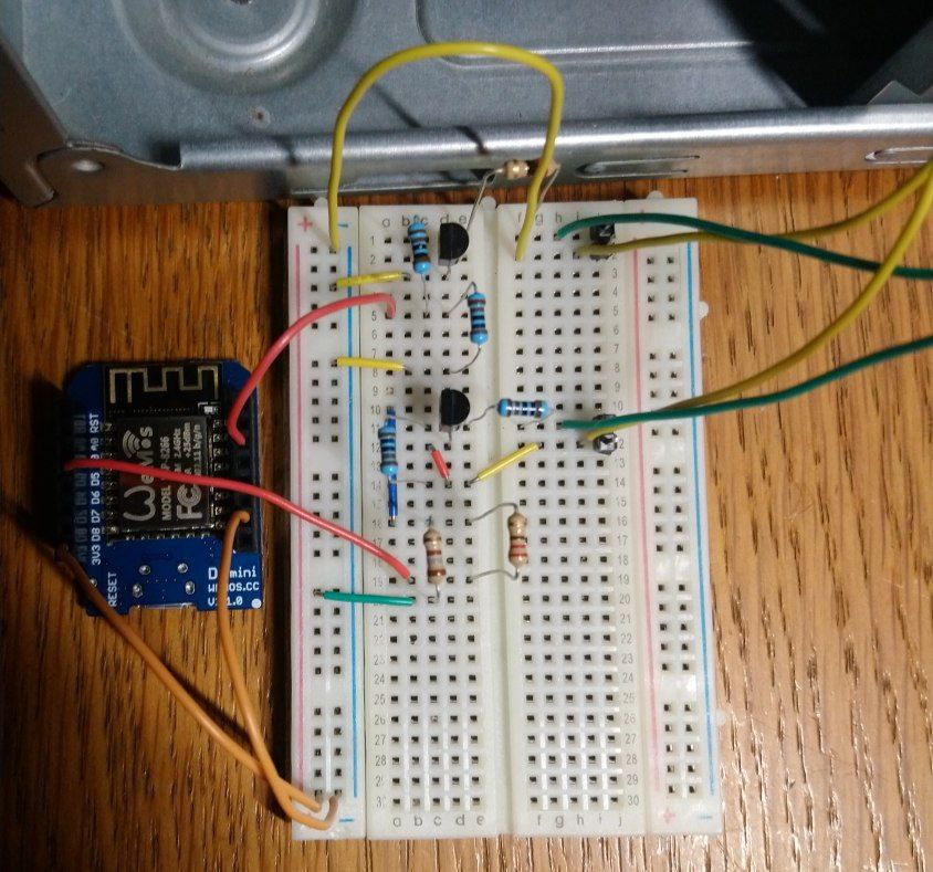
To try out if the circuit worked, I prototyped it on the so-called breadboard4 and it did! I will describe in the next section the code which runs on the microcontroller.
Putting it all together
The final step, after having the circuit diagram sorted out and tested, is to solder all the components to make the connections between them more reliable and more compact: I used a shield board for my WeMos D1 Mini, a sort of hat of the exact size of the microcontroller’s board, which can be stacked on top of it.
The final result is the following; I am not an expert but I managed to make it through this task with a couple of failed routings and a couple of hours. My advice on such soldering work is
“Don’t be afraid of making mistakes, but rather beware the hot tip of the soldering iron!”
| Front | Back |
|---|---|
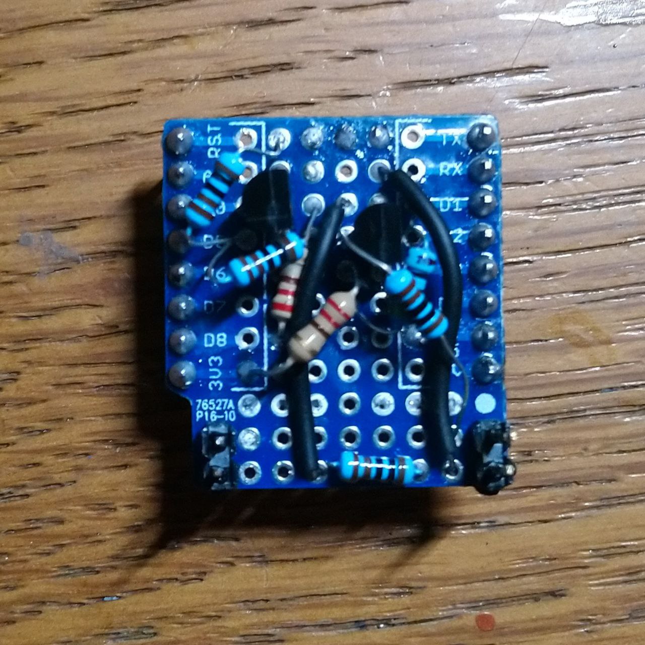 | 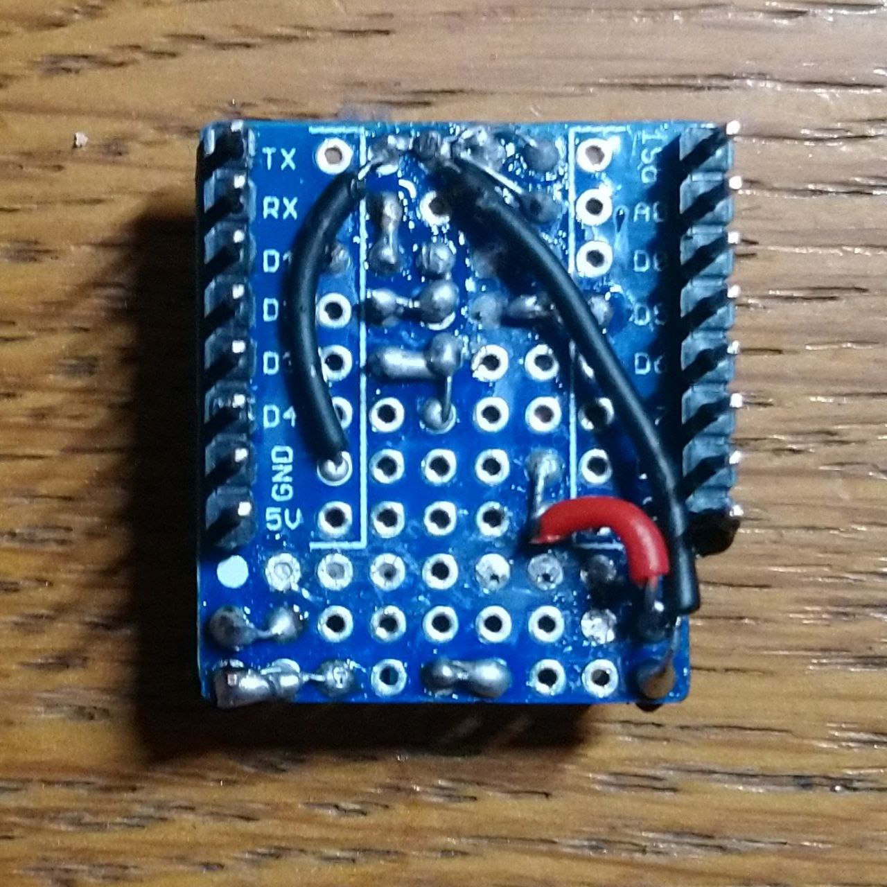 |
After trying to route stuff on the shield board I ended up swapping the layout, in fact wiring the D1 pin to the PWR_LED and the D5 pin to the PWR_SW; however, the rest of the circuit did not change.
NOTE: Before placing the microcontroller with this shield on top inside the computer case, I wrapped the whole thing in duct tape, to have some sort of dielectric protection.
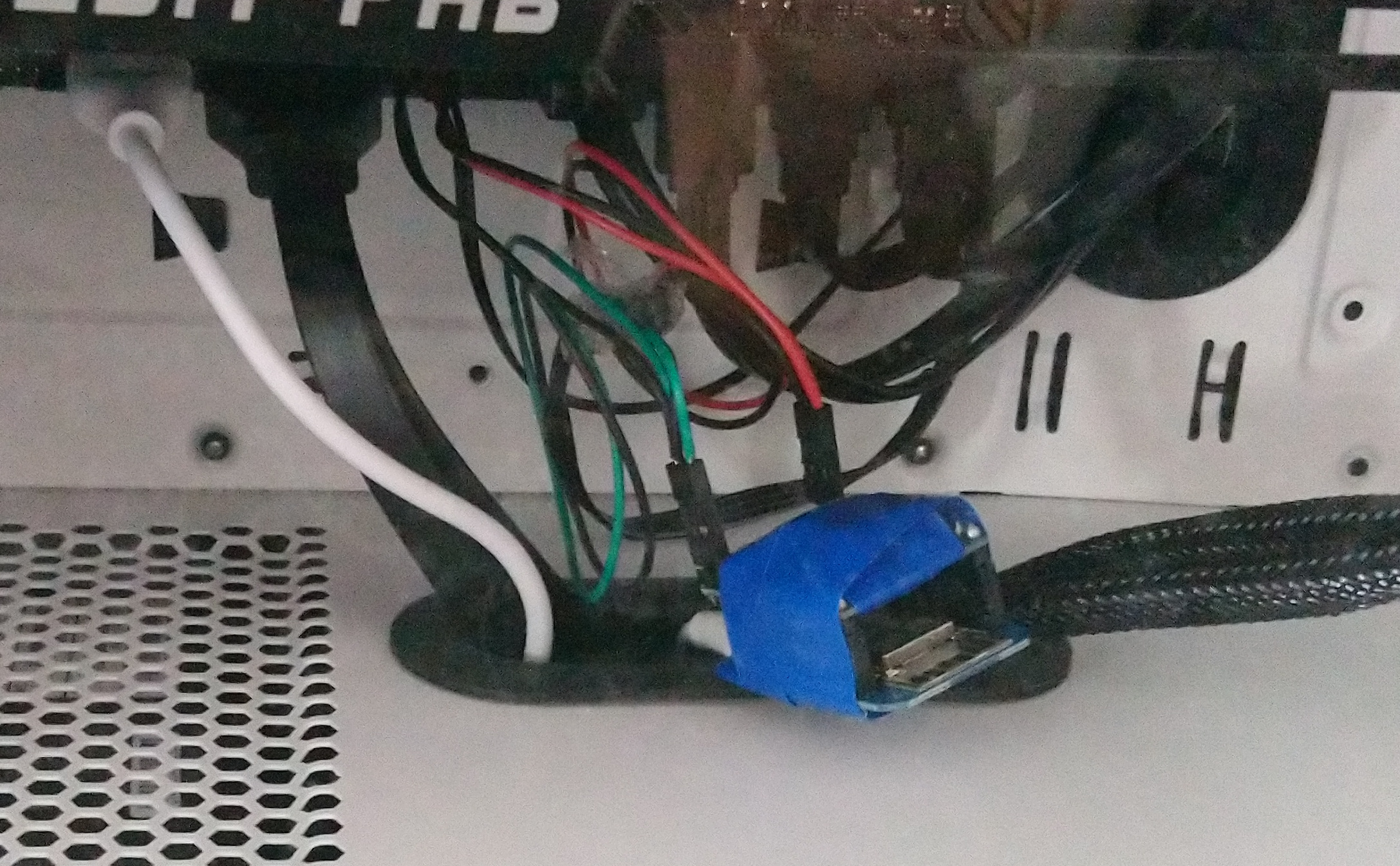
Circuit powering
To power the microcontroller I used a motherboard adapter from USB header to USB female port, in which I then plugged the cable connected to the microcontroller’s MicroUSB port. Also, I had to enable the “Standby USB power” option from the motherboard’s BIOS, to keep on any connected peripheral when the computer is off but the power supply is on.
Flashing the software
I wrote the program to operate the microcontroller and flashed it to the Wemos D1 Mini through the Arduino IDE software: the support for the ESP8266 platform is well established and also I had experience working with it.
You can review the code I used from my GitHub repository ans learn more about the requirements to compile it through the Arduino IDE; basically, I am reading the D1 pin voltage to check the power status of the motherboard, and I’m setting high voltage to the D5 pin to close the power button circuit: this second part is the tricky one, since you are also supposed to release the power button and therefore the D5 pin should also be set to low voltage after a short delay.
Moreover, I wanted to log the last time the power status was changed and interact with the power button over Wi-Fi, and finally update the code over Wi-Fi as well, since it would be inconvenient to pull the device out of the computer case every time I want to update it.
I could accomplish this using NTP to get the current time, and leveraging the following great libraries from GitHub user ayushsharma82:
- AsyncElegantOTA allows to send a new firmware to the microcontroller through Wi-Fi
- ESP-DASH runs a web server on the microcontroller with a dashboard interface
- ESPConnect puts the microcontroller in access point mode when it cannot connect to Wi-Fi, allowing configuration without cables
Conclusions and credits
I had a lot of fun building this project, and I was admittedly inspired by this post on Hackster blog by the user Zvonko Bockaj; take a look at his work too, since he added MQTT capabilities to his microcontroller to interact with it even from outside its network - while I wanted instead a stand-alone device. There is also some discussion around the method to power the circuit and how to improve it, which I could try in another iteration.
Below you can see the ESP ATX WoWL in action (naming things is difficult, OK?):
The Wake on LAN (WoL) standard, when implemented, enables a device to be fully turned on from a low power state through the reception of a specific message over its network interface. ↩︎
Bipolar junction transistors (BJTs) are triode components controlled with current applied to their “base” terminal; moreover, a negative-positive-negative (NPN) configured transistor has its “base” terminal positively polarized and the other two negatively. ↩︎
Light emitting diodes (LEDs) have polarized terminals: the cathode is the negative one, and is the terminal at the head of the arrow of the LED symbol. ↩︎
A breadboard is a tool to connect the small terminals of components in a structured manner, without soldering; it exposes horizontal terminal strips and vertical power rails. ↩︎